Design & CAD
SolidWorks, mechanical assemblies, engineering drawings, GD&T, ASME Y14.5, design iteration.
MECHANICAL ENGINEERING PORTFOLIO
Fourth-year Mechanical Engineering student at UC Irvine nearing graduation with hands-on experience in mechanical design, manufacturing, CAD, and practical engineering problem solving.
I am currently seeking full-time mechanical engineering opportunities in design,
manufacturing, product development, testing, or production support where I can apply
my skills for gainful employment.
I have a strong passion for getting involved in all processes of engineering in my professional and personal life. I enjoy off-roading and exploring
automotive design and vehicle-based mechanisms in my free time, as well as exploring nature and camping.
SKILLS SNAPSHOT
SolidWorks, mechanical assemblies, engineering drawings, GD&T, ASME Y14.5, design iteration.
3D printing, laser cutting, welding, shop-floor tooling, fixtures, fabrication, production support.
FEA, design validation, prototype testing, troubleshooting, performance improvement, documentation.
BACKGROUND
My academic and professional background is focused on mechanical design, manufacturing, prototyping, testing, and hands-on engineering problem solving.
B.S. Mechanical Engineering
Expected Graduation: June 2026
GPA: 3.25
Mechanical engineering undergraduate with coursework and project experience in mechanical design, manufacturing, CAD, finite element analysis, thermodynamics, heat transfer, fluids, dynamics, and controls.
Relevant coursework: Mechanical Behavior and Design Principles, Computer-Aided Engineering, Theory of Machines, Heat and Mass Transfer, Vibrations, Special Topics in Fabrication Safety - Welding, Thermodynamics, Calculus, Linear Algebra, Fluid Dynamics
RBC Transport Dynamics — Santa Ana, CA
June 2025 – Present
FEATURED WORKS
A collection of personal and academic engineering projects focused on mechanical design, analysis, fabrication, prototyping, troubleshooting, and product development.
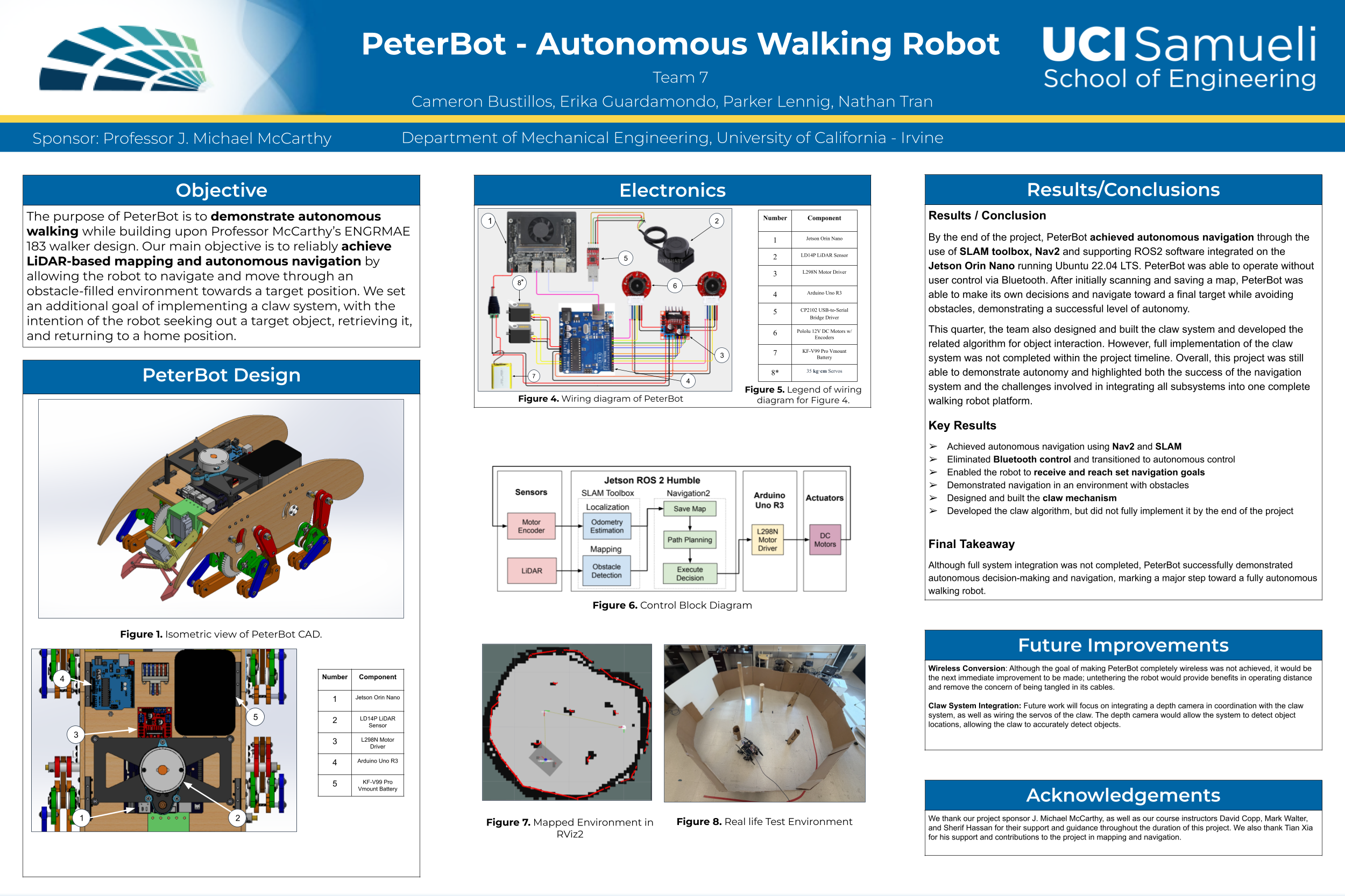
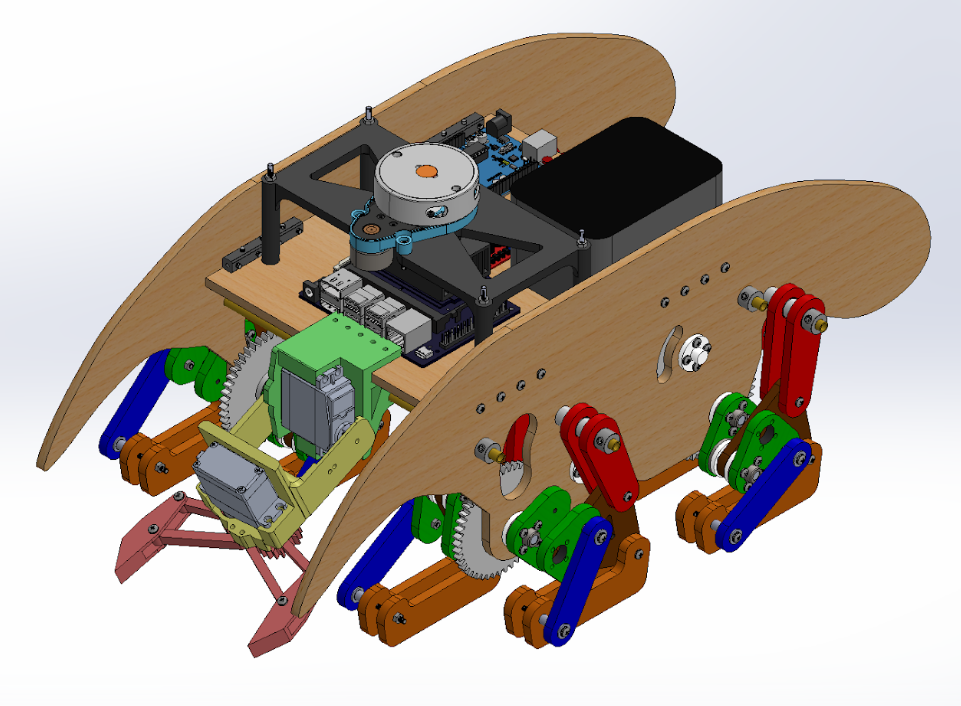
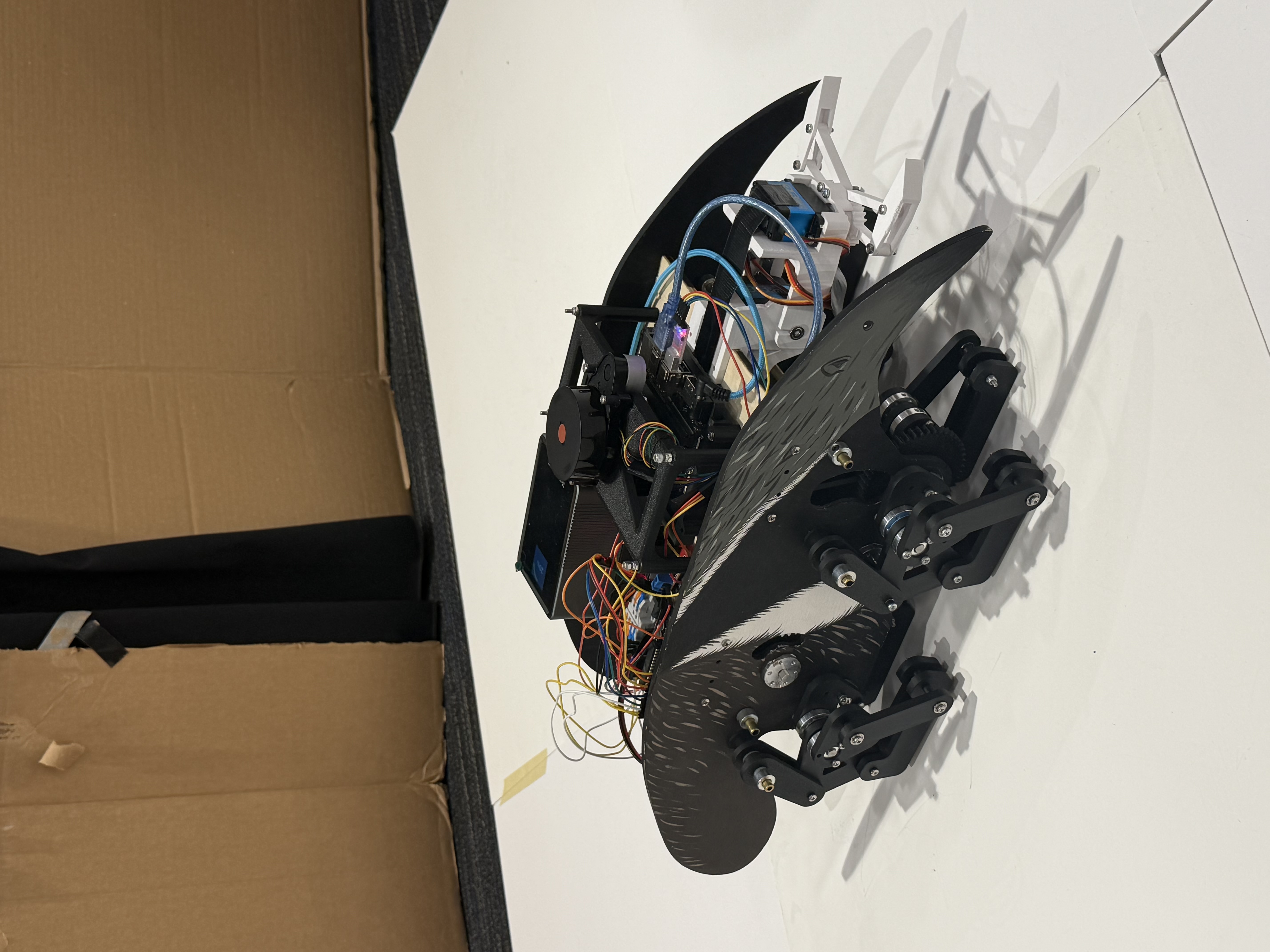
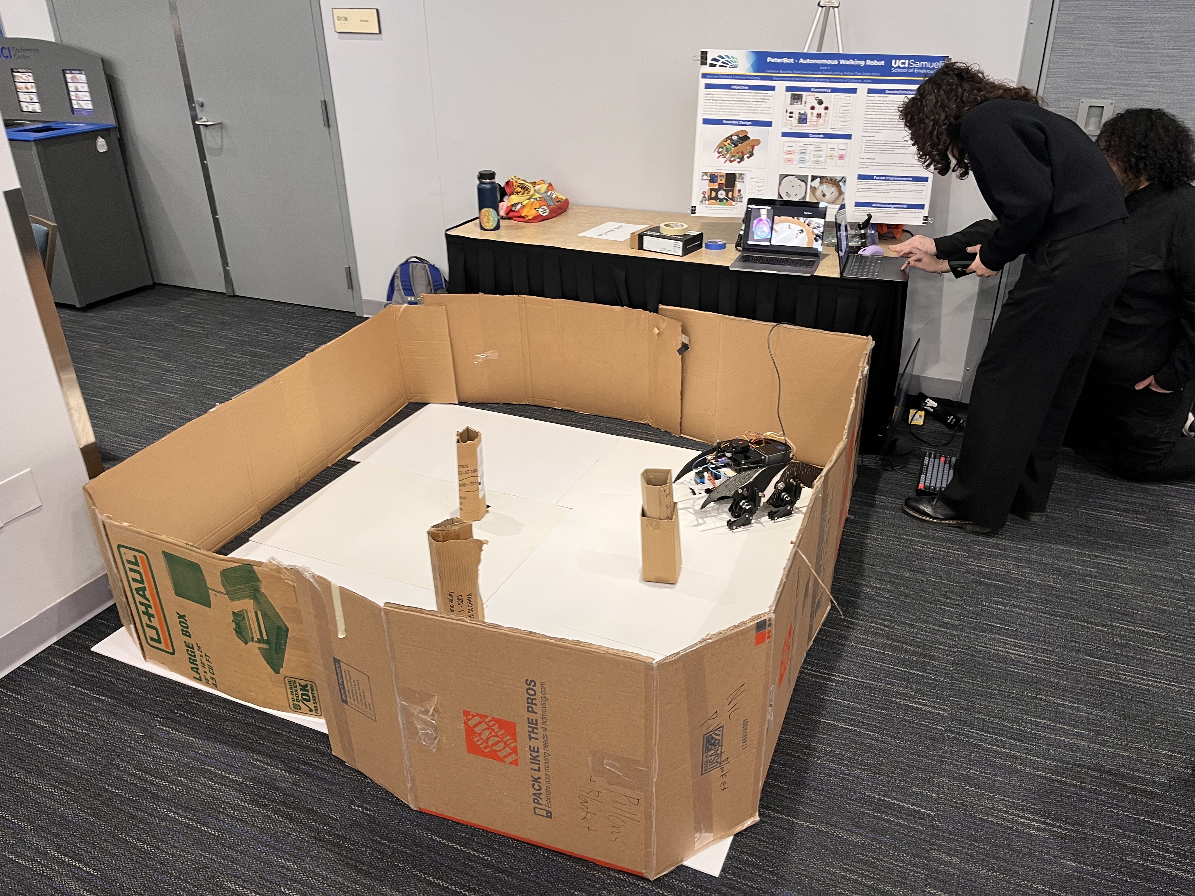
School Design & Manufacturing Project
Role: Mechanical Lead.
Objective: Develop, manufacture, and test an autonomous walking robot using leg linkages
and drivetrains from our sponsor, Professor J. Michael McCarthy. The goal was to achieve repeatable walking
motion while using LiDAR to map the environment and autonomously navigate around obstacles.
Results: Designed the robot in SolidWorks, manufactured the mechanical assembly, improved
chassis rigidity using brass rods, and integrated mounts for the LiDAR sensor, Jetson Orin Nano controller,
and supporting hardware. The robot successfully demonstrated autonomous navigation at UC Irvine's Annual
Design Review.
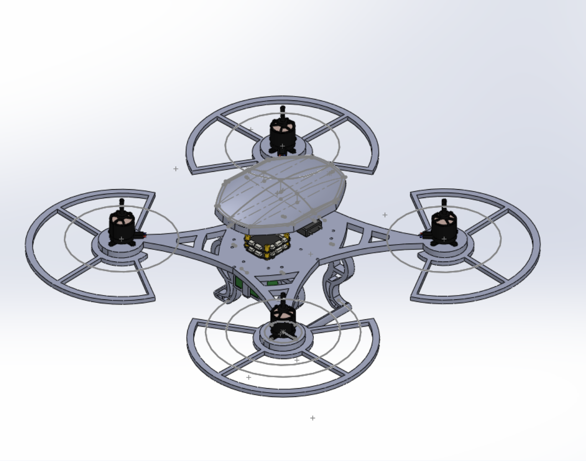
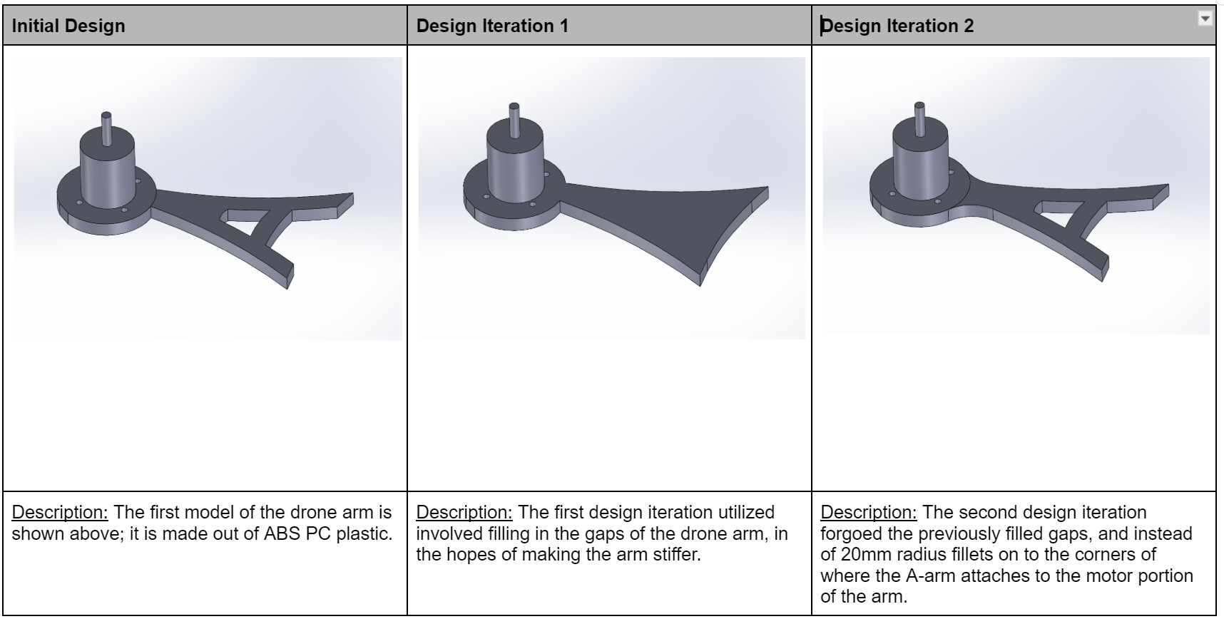
School Design, Simulation Project
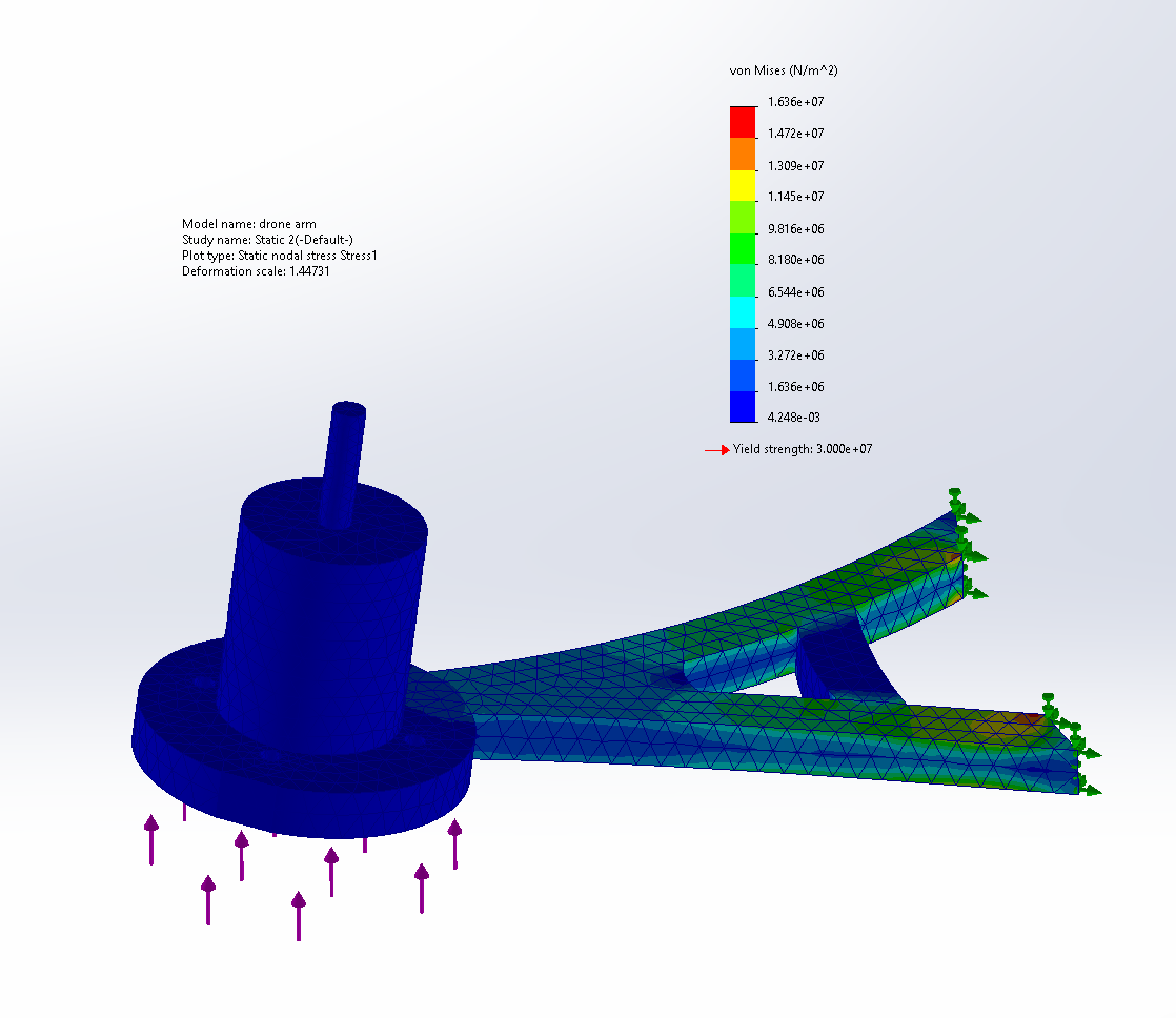
Objective: Evaluate and improve the structural performance of a quadcopter drone arm using finite element analysis
in SolidWorks. The project focused on identifying high-stress regions under representative loading conditions (hovering thrust and
lateral impact), then iteratively refining the geometry to reduce stress concentrations, improve stiffness, and maintain manufacturability.
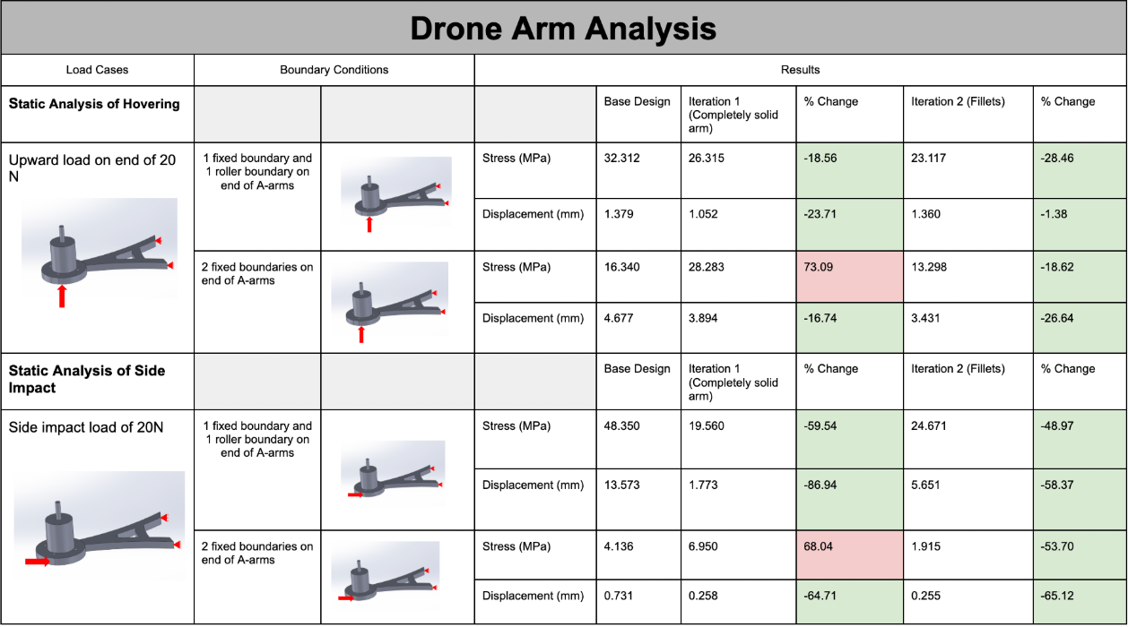
Results: Conducted multiple design iterations, including a fully solid arm and a filleted geometry, to reduce stress
concentrations and improve structural performance. Finite element analysis showed up to ~60% reduction in von Mises stress in critical
regions under both vertical (hover) and lateral (impact) loading conditions, along with up to ~85% reduction in displacement in certain
cases, significantly increasing stiffness. The final design maintained stresses well below material yield strength while achieving more
uniform load distribution, with filleting and improved load paths identified as key contributors to the overall performance gains.
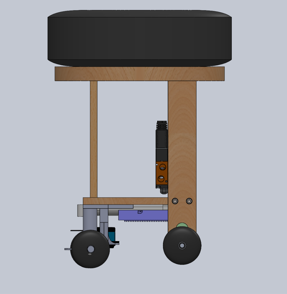
School Design & Manufacturing Project
Role: Mechanical Lead.
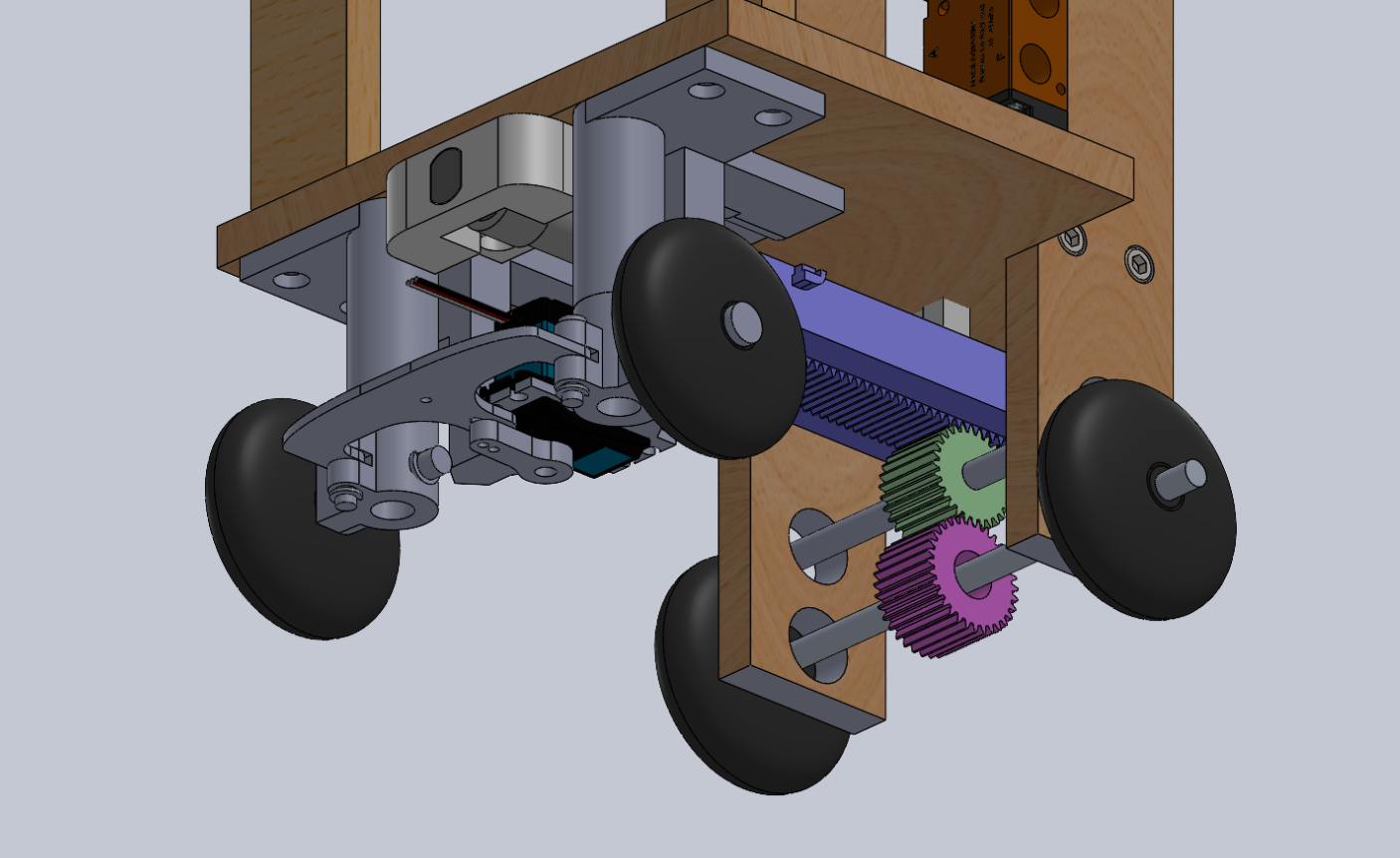
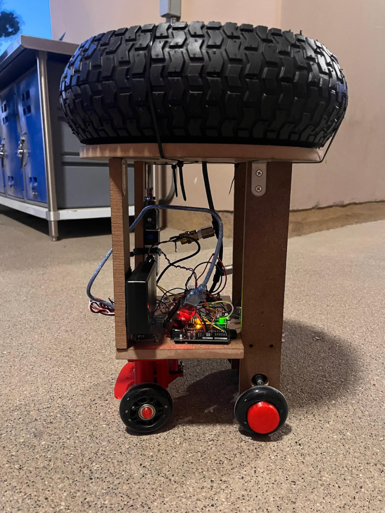
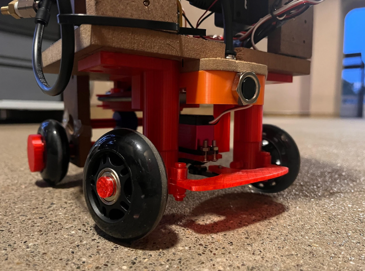
Objective: Design and manufacture a pneumatic-powered robot capable of steering and propelling
itself through an obstacle course while meeting size and compressed-air power constraints.
Results: Designed a wooden chassis, rack-and-pinion drive system, and 3D-printed steering
system controlled by a servo. The final robot reached 1.2 ft/s and achieved a steering range of 110 degrees.
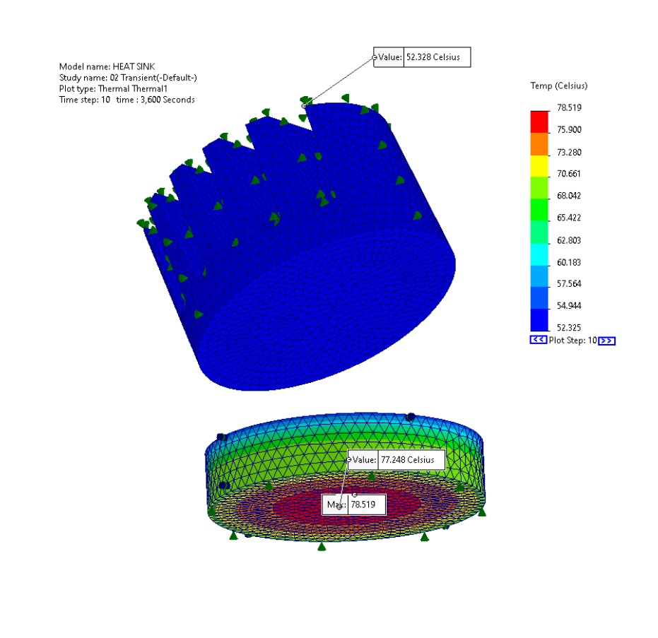
School Simulation Project
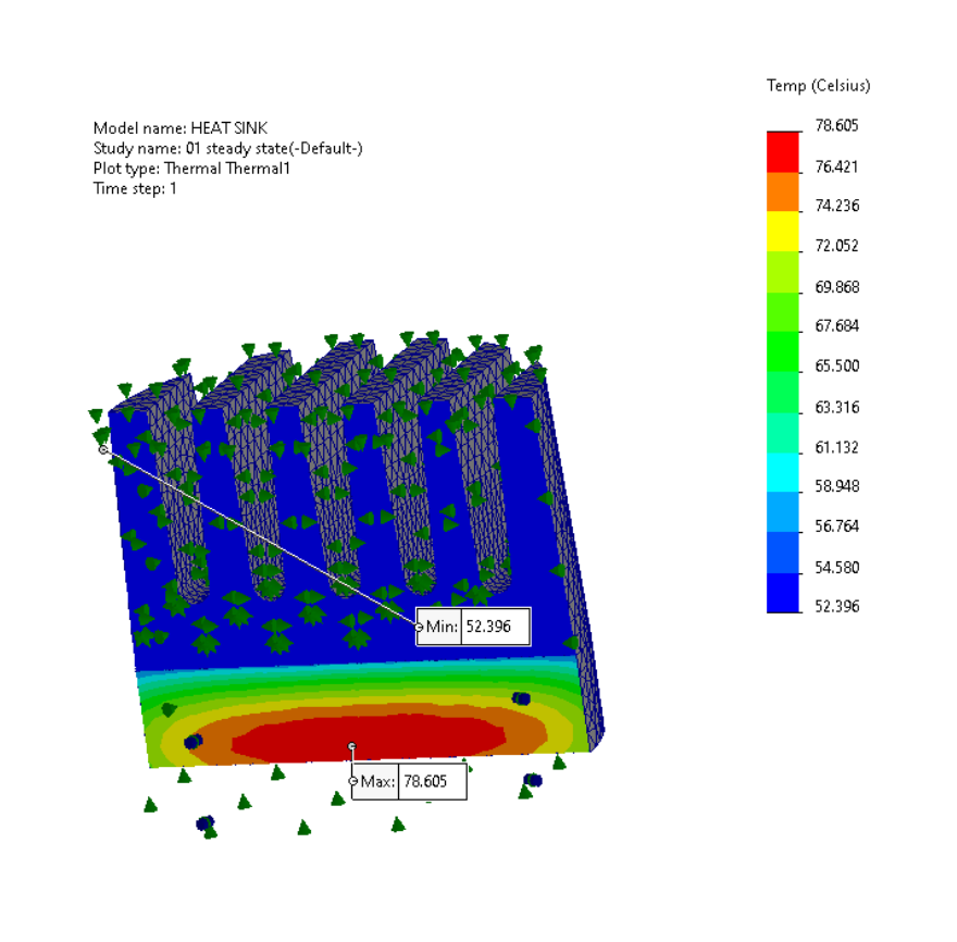
Objective: Perform steady-state and transient thermal simulations of a ceramic porcelain microchip
bonded to a 1060 aluminum alloy radiator using thermal boundary conditions representative of electronic heat dissipation.
The microchip shall be modeled with a uniform 25 W heat load, convection across exposed surfaces, and distributed thermal contact
resistance between the chip and heat sink interface.
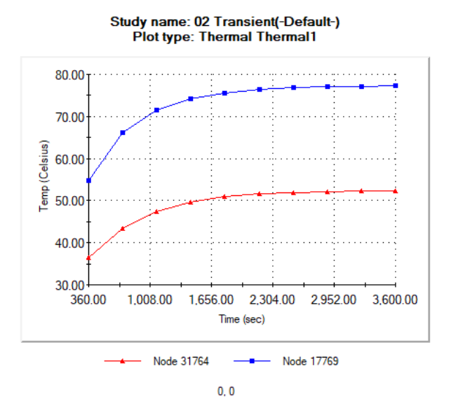
Results: The steady-state study evaluated final temperature distribution throughout the assembly,
while the transient study modeled the system response from an initial temperature of 300 K over 3,600 seconds using
360-second time steps. Results showed a maximum assembly temperature of 78.519°C and a minimum temperature of 52.328°C.
Probe data from the bottom center of the microchip and the tip of a radiator fin showed the system approaching steady-state
temperatures of approximately 77°C and 52°C, respectively, demonstrating a 25°C thermal gradient between the heat source and cooling fin.
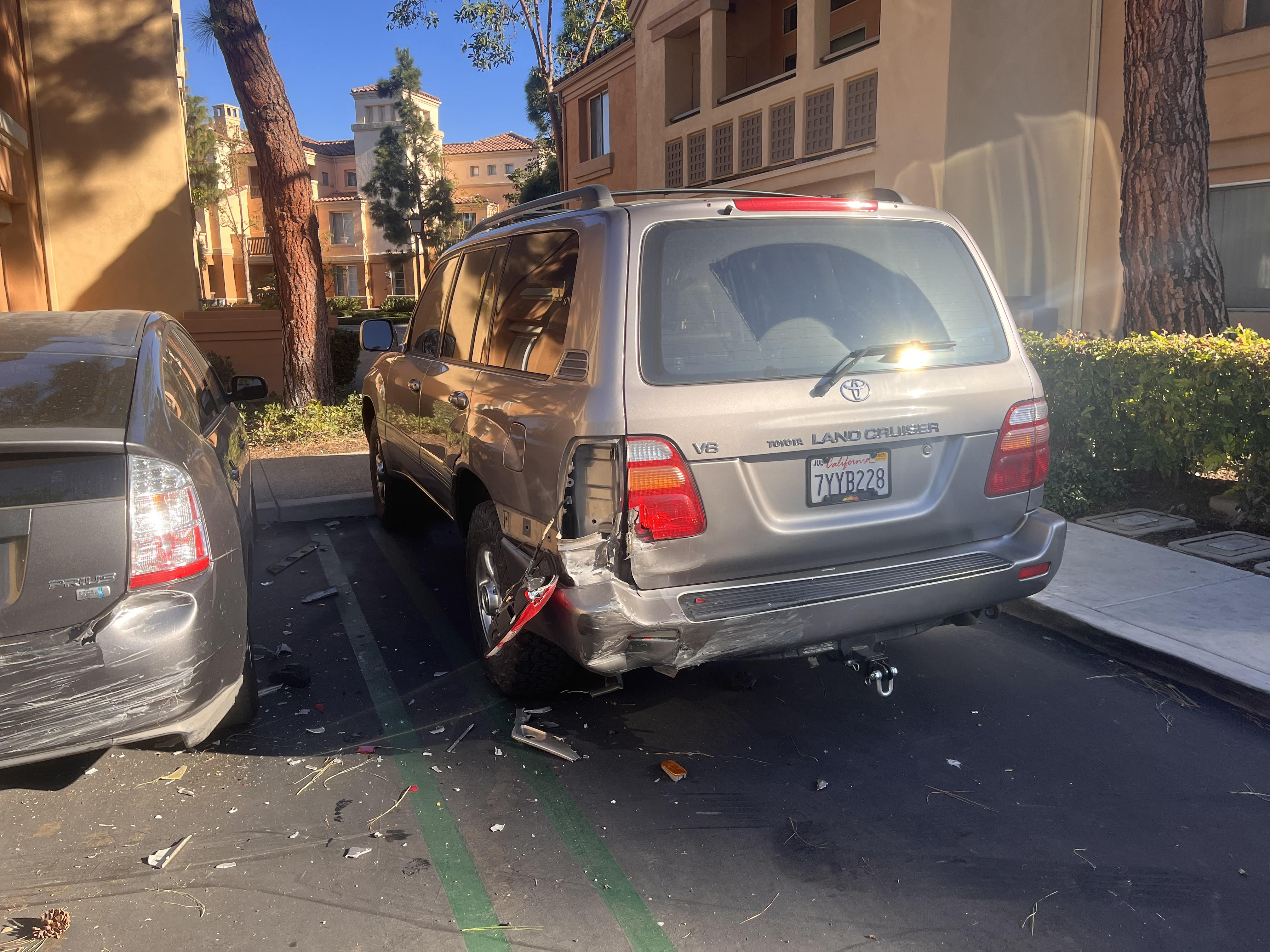
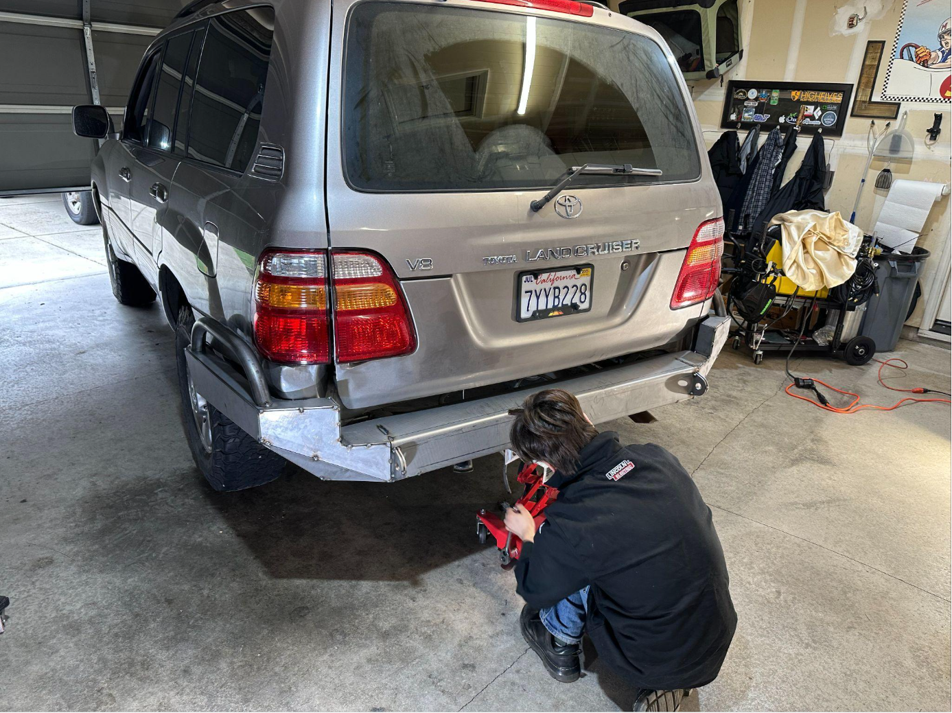
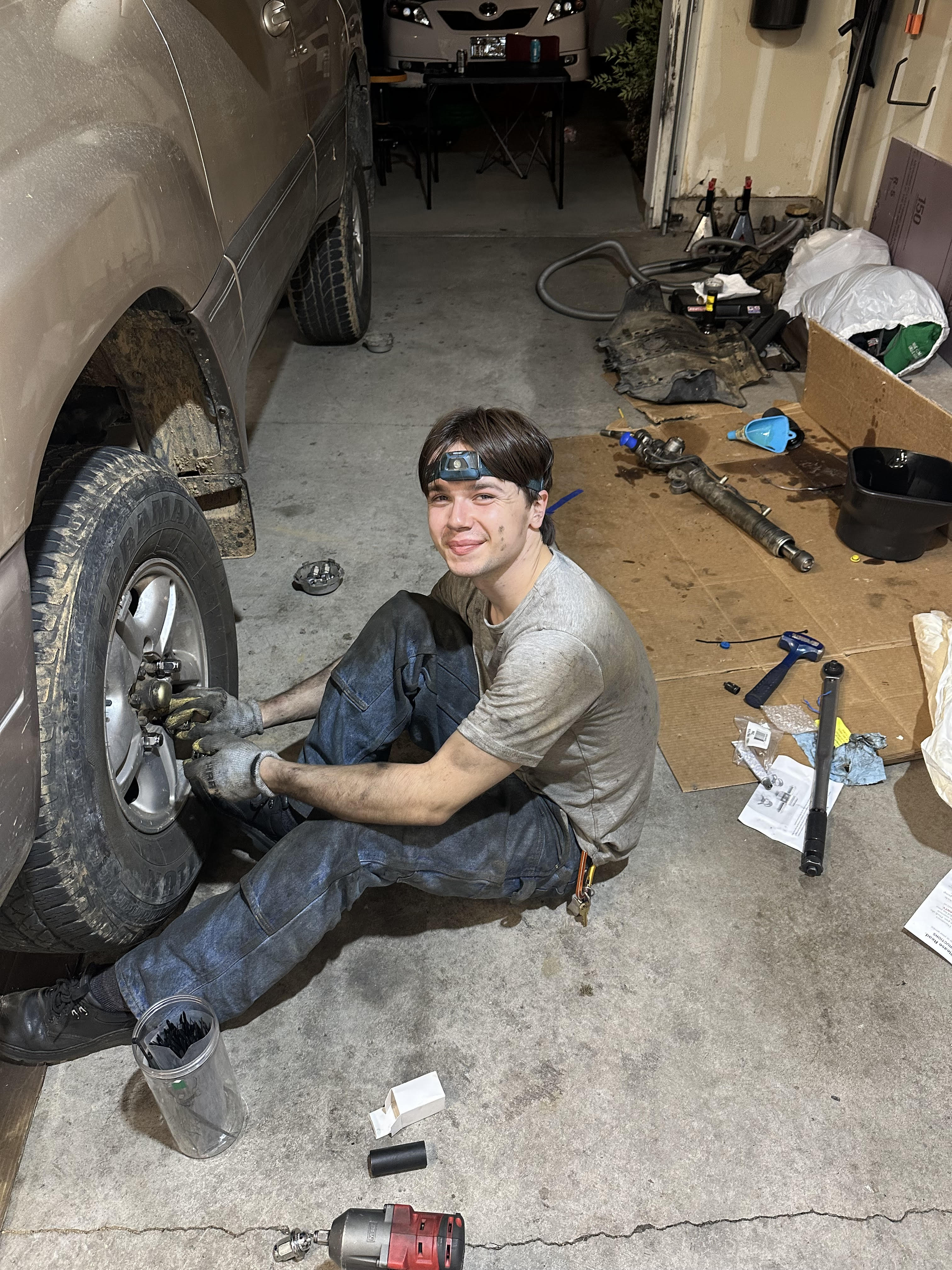
Personal Manufacturing Project
Objective: Repair collision damage on my personal vehicle, replace the damaged rear bumper,
paint and weather-seal repaired components, and fabricate a stronger rear bumper within a limited budget.
Results: Completed body repair and fabricated a 3/16-inch mild-steel rear bumper under a
$3,500 budget, reducing the estimated repair cost from approximately $11,000 to about $2,800.
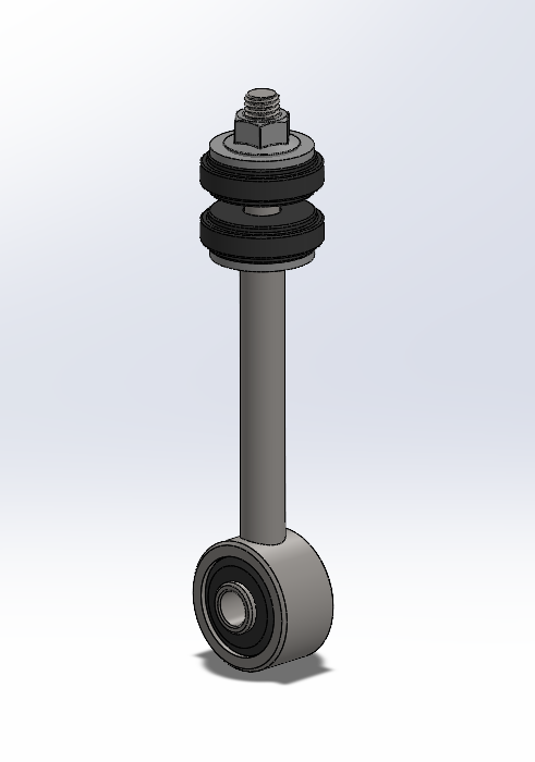
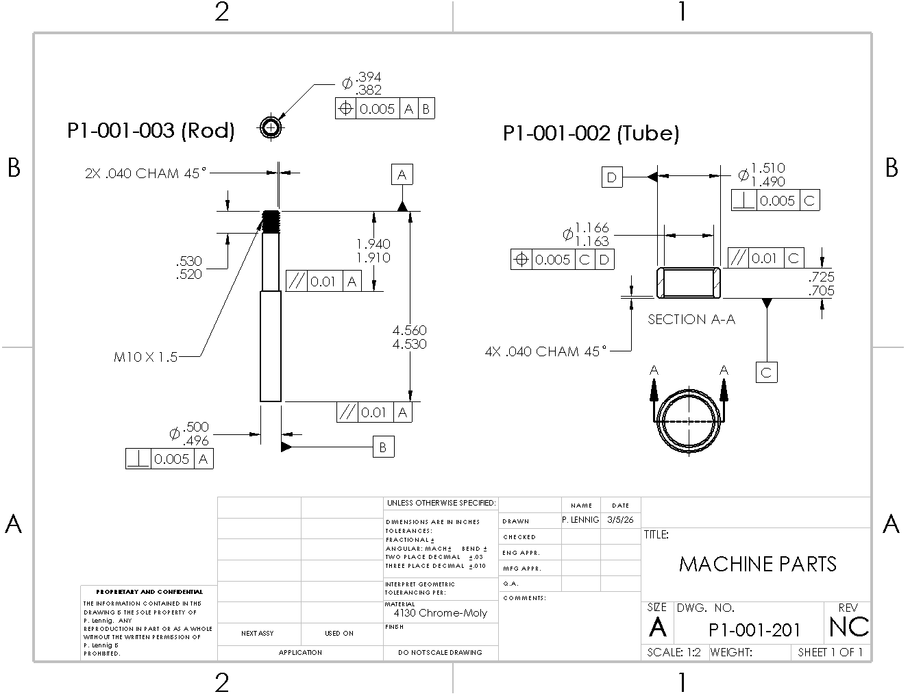
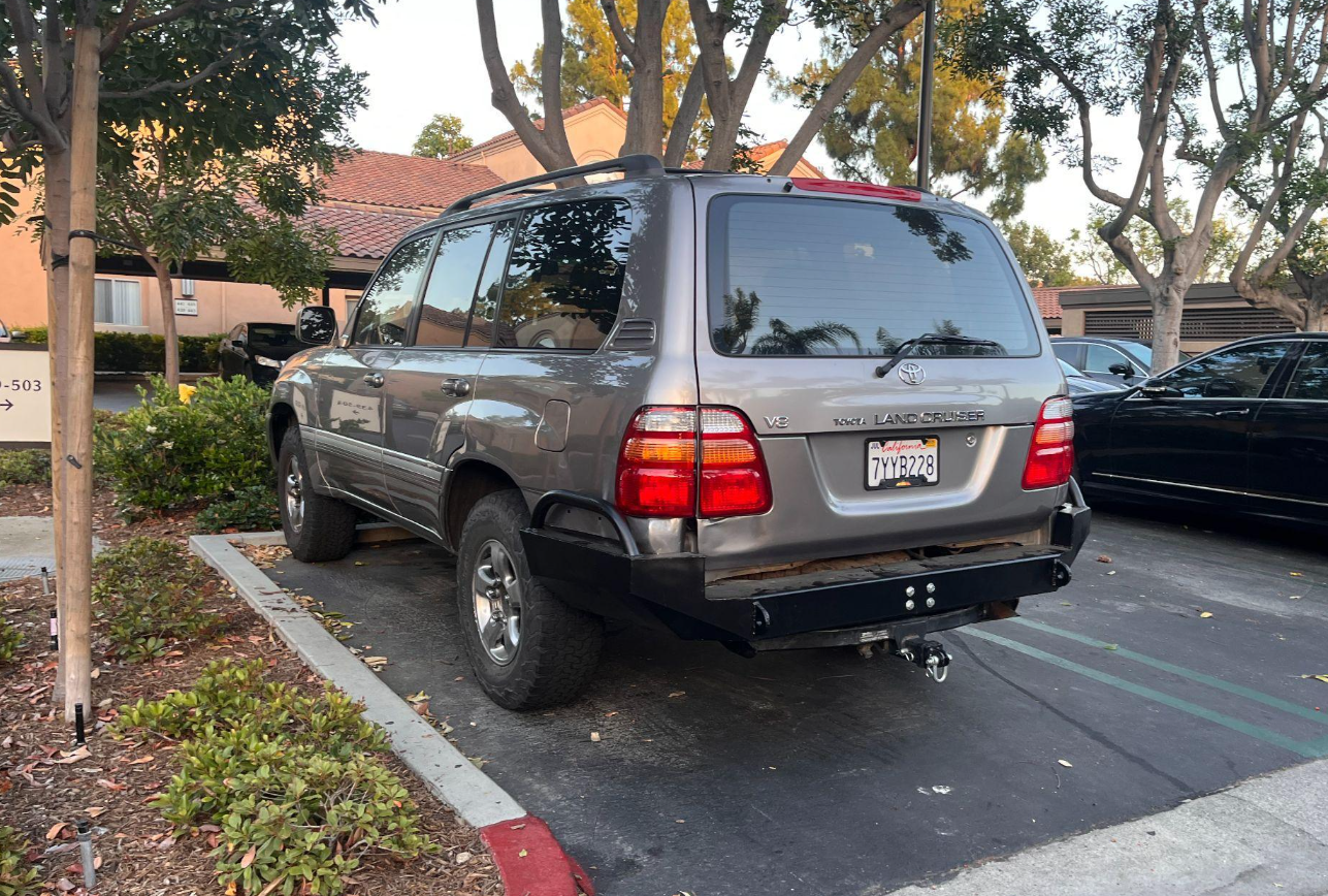
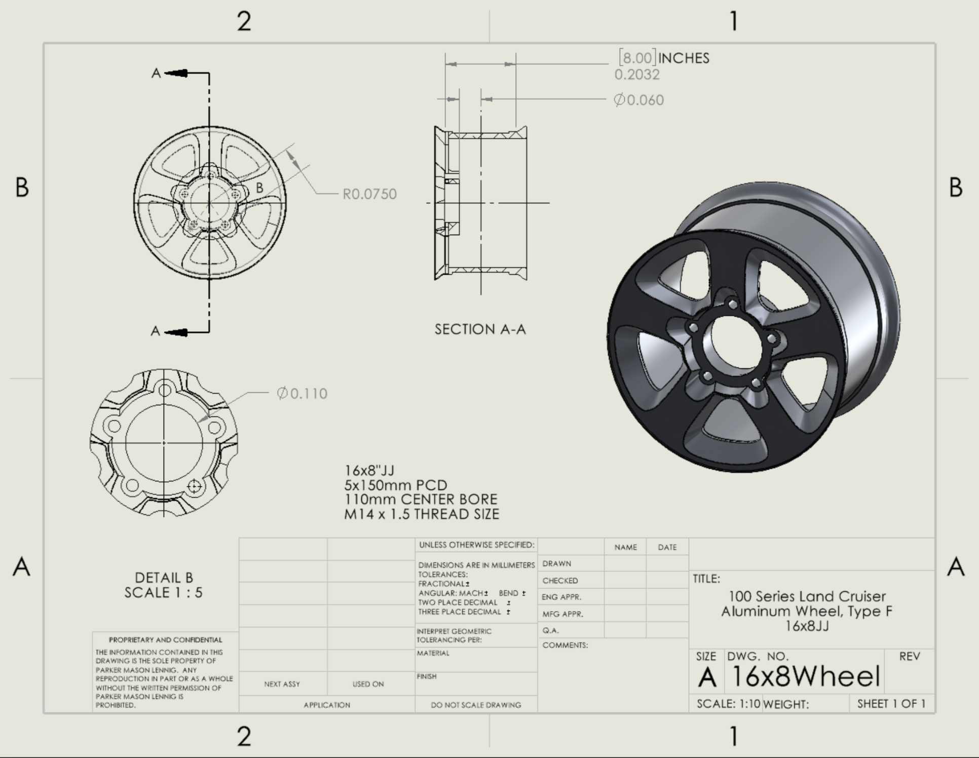
Personal Design Project
Objective: Design extended sway bar end links to reduce suspension binding and restore safer
suspension geometry on a vehicle lifted by 2 inches.
Results: Modeled the components and developed manufacturing drawings using GD&T for
100-series chassis sway bar end links. The design was developed to restore OEM-style geometry after a
suspension lift and prepare the parts for future fabrication.
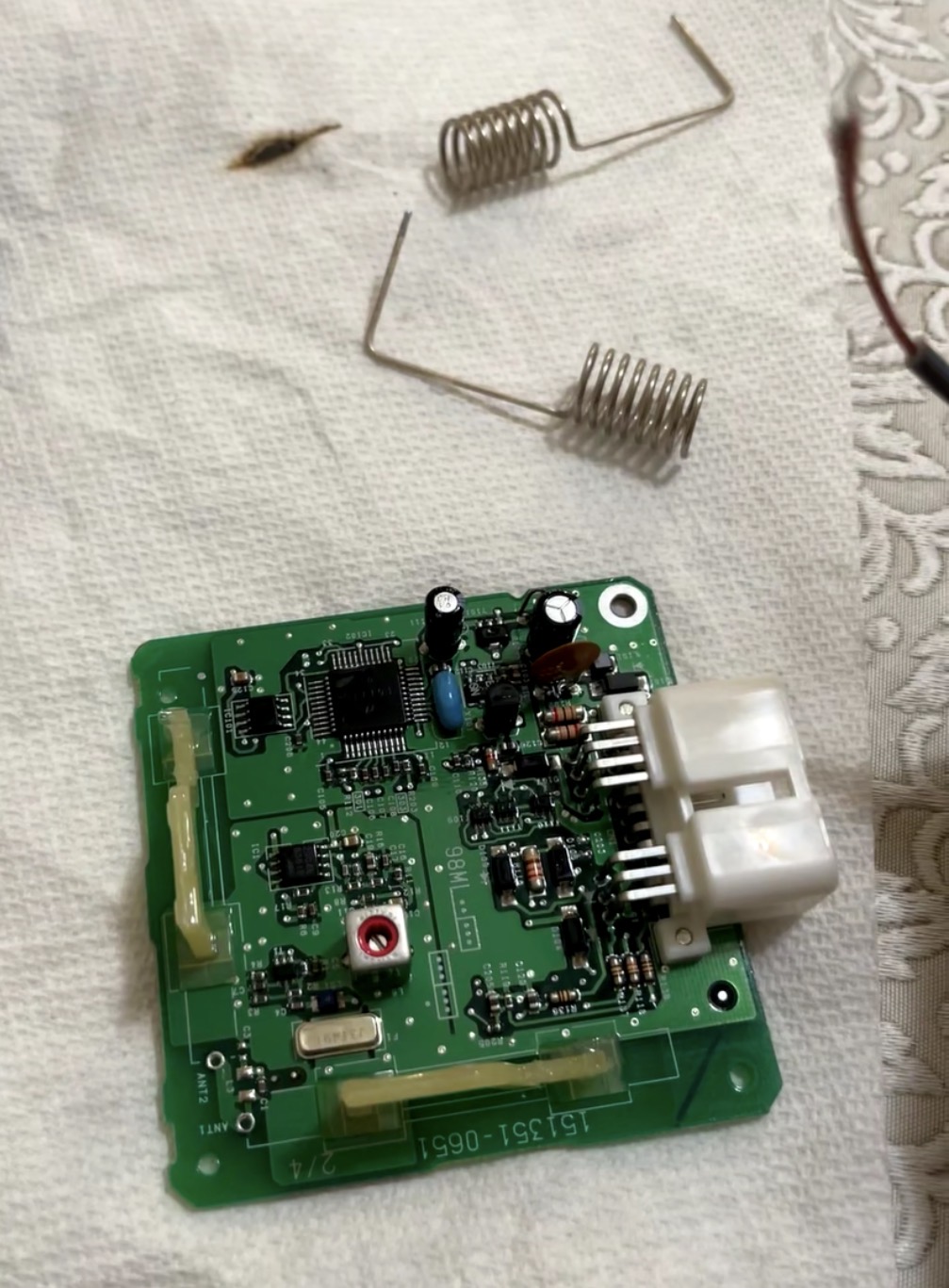
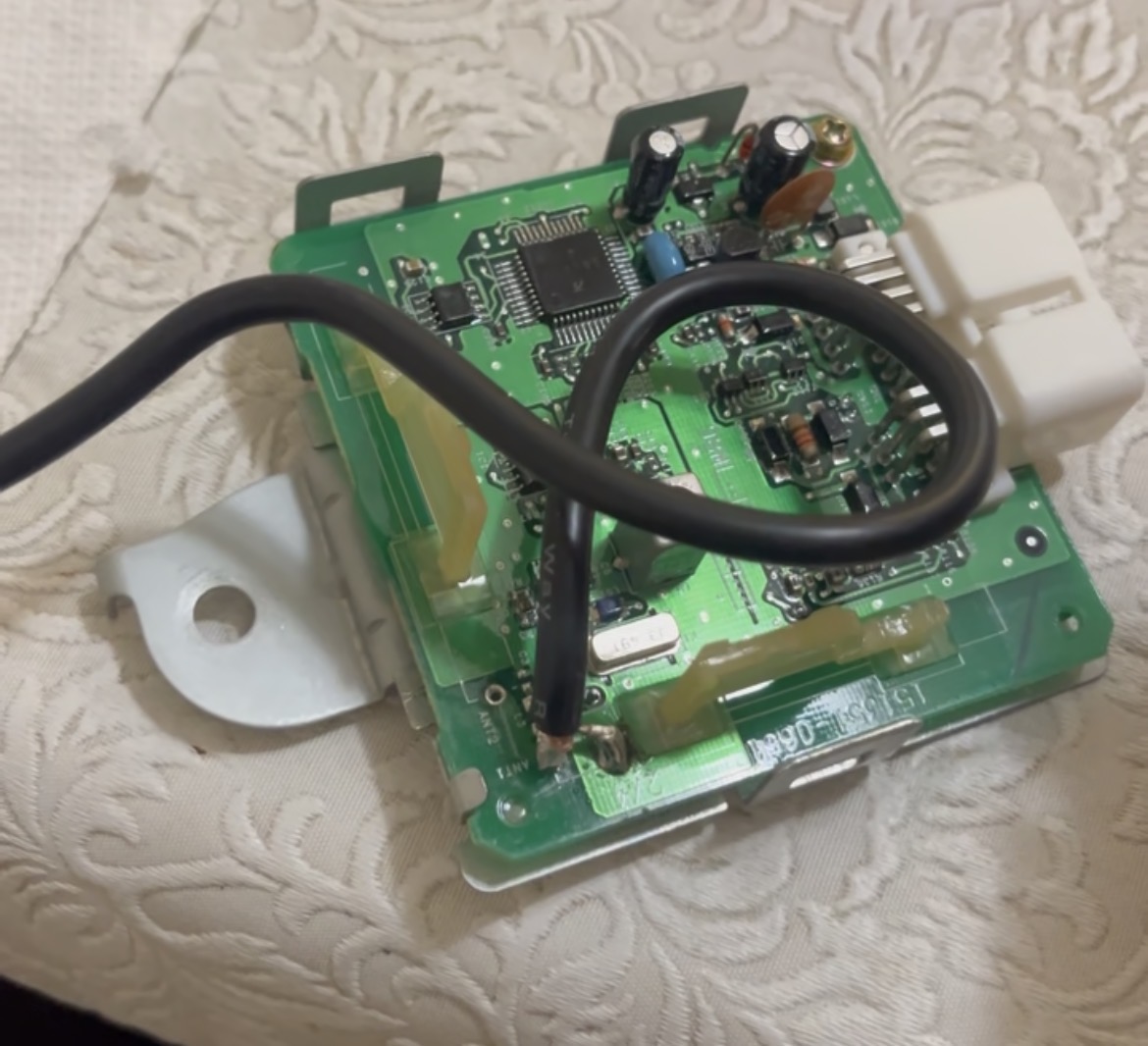
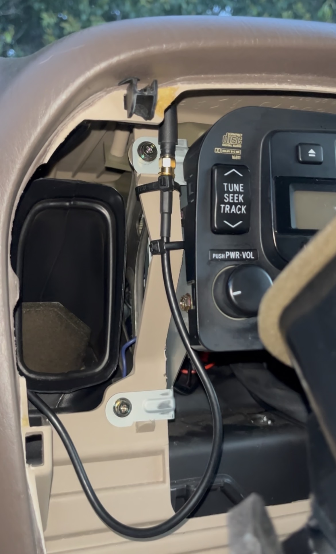
Personal Design & Manufacturing Project
Objective: Improve the range and reliability of a vehicle key fob by replacing the factory
receiver antenna with a stronger 315 MHz antenna.
Results: Removed the factory antenna, soldered in an upgraded antenna, and increased key fob
operating range to approximately a 50-foot radius around the vehicle for a total cost of about $18.
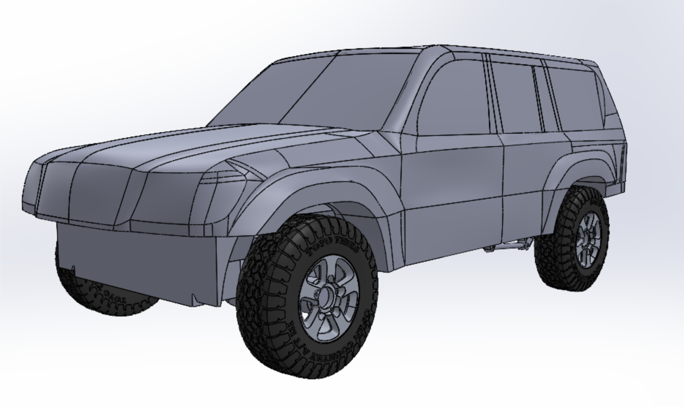
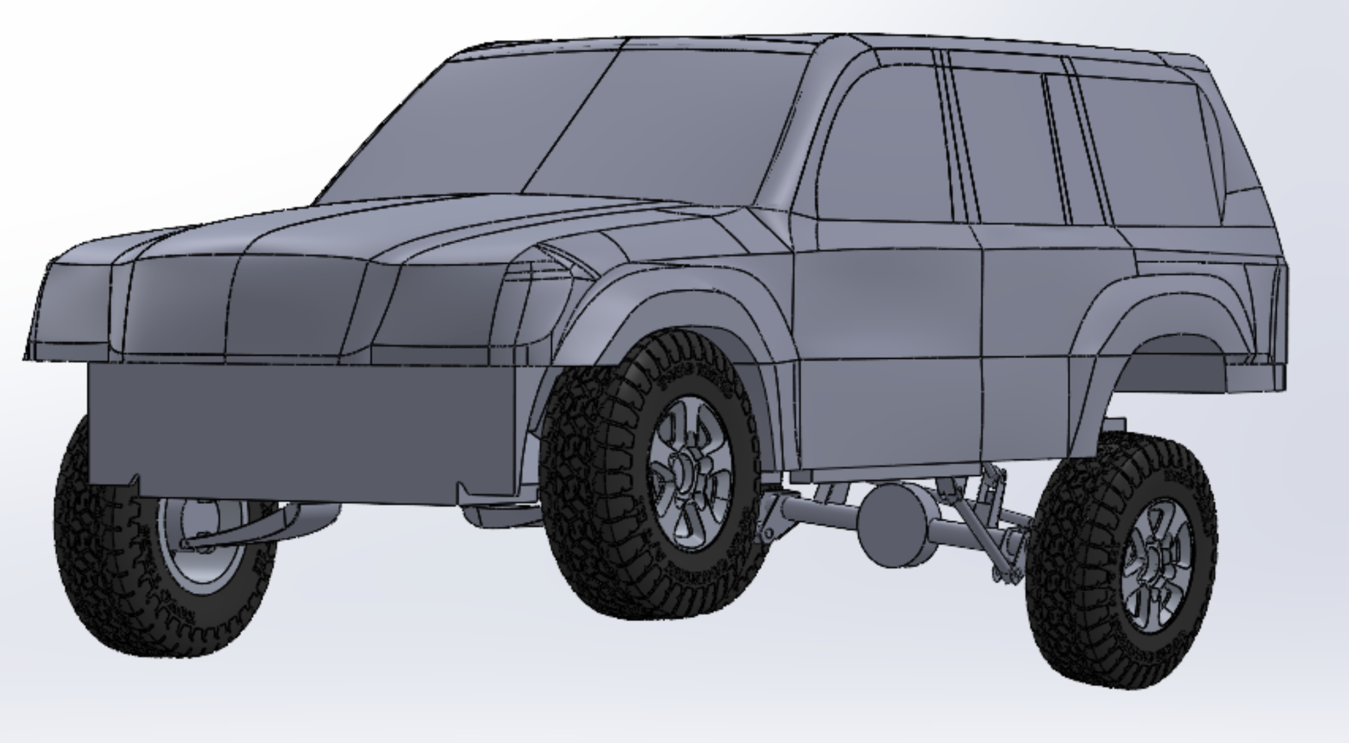
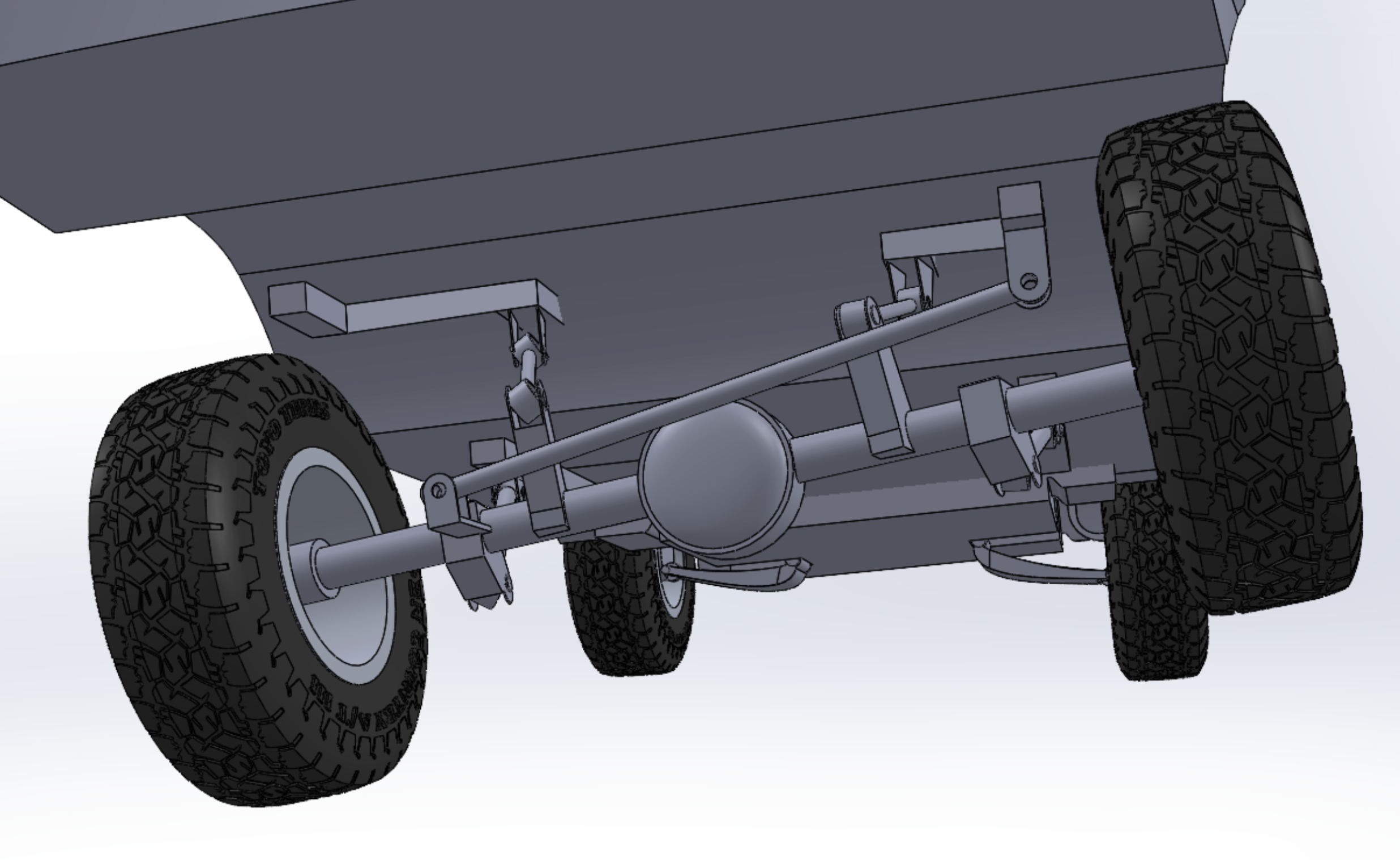
Personal Design Project
Objective: Model the front and rear suspension of my personal vehicle to better understand
suspension motion, articulation, and packaging for future bumper and accessory design.
Results: Created a SolidWorks model that achieved 7.5 inches of front suspension travel and
15 inches of rear suspension travel while also modeling the factory 16-inch wheels and 275/70R16 tires.
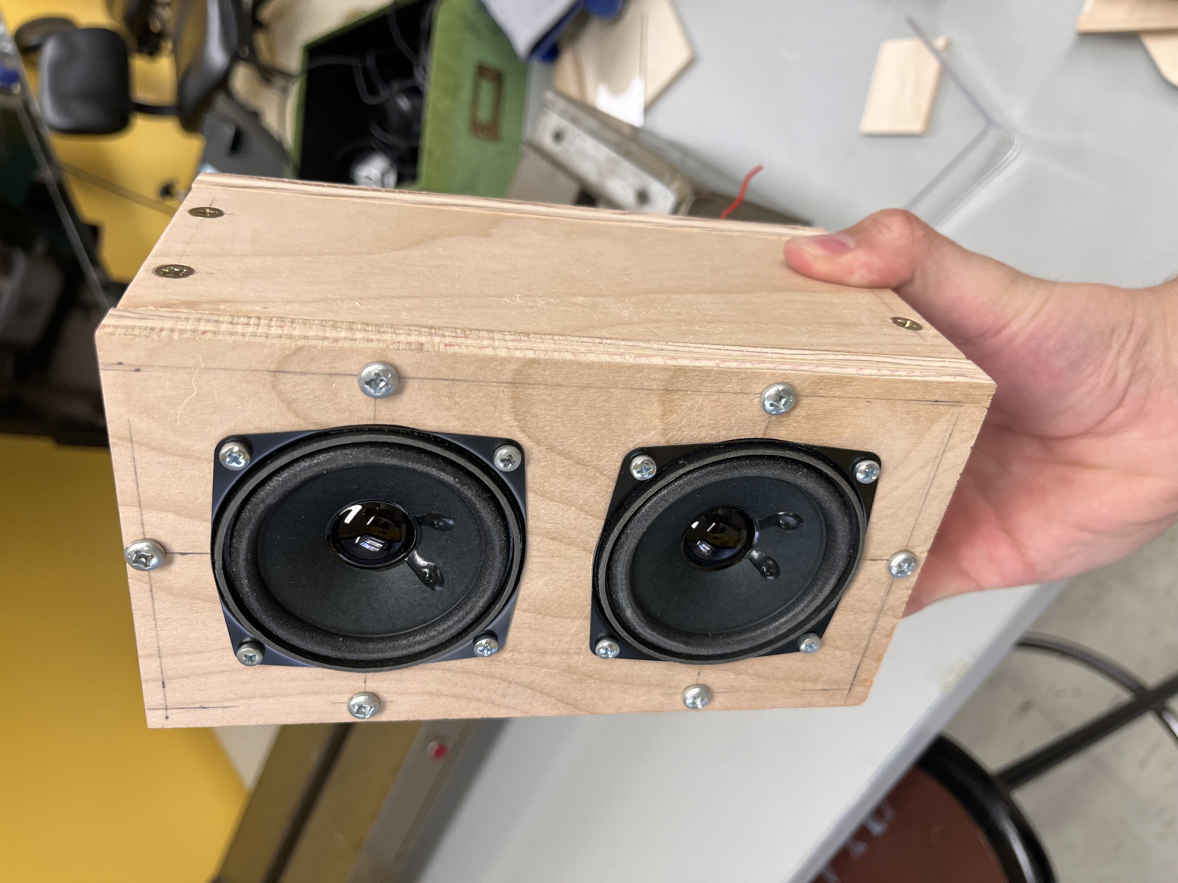
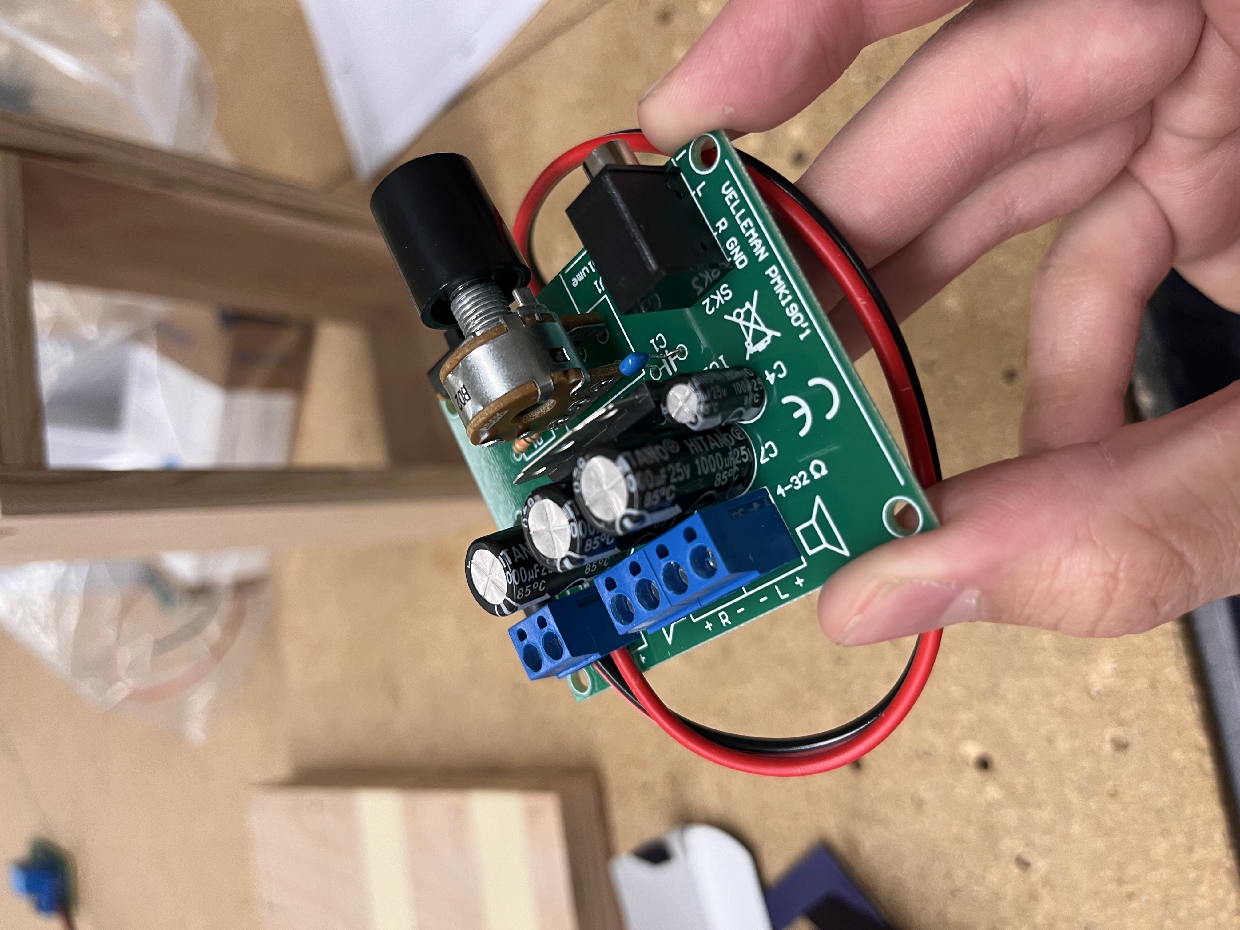
School Manufacturing Project
Objective: Manufacture a dual-woofer Bluetooth speaker by soldering the control circuit board,
fabricating the wooden enclosure, and assembling all components.
Results: Built a functional Bluetooth speaker with approximately 30 feet of wireless range,
clean build quality, and acoustic foam added to reduce box resonance.
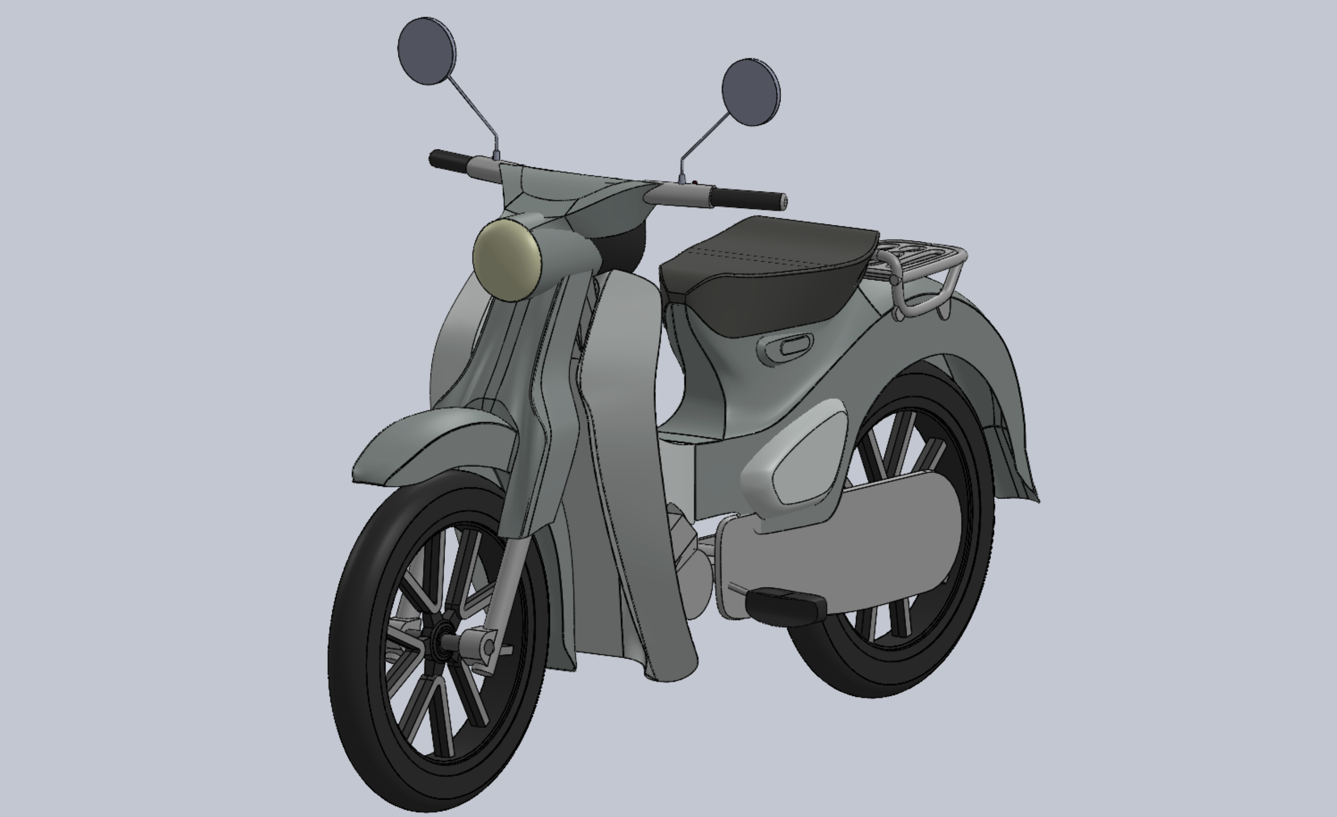
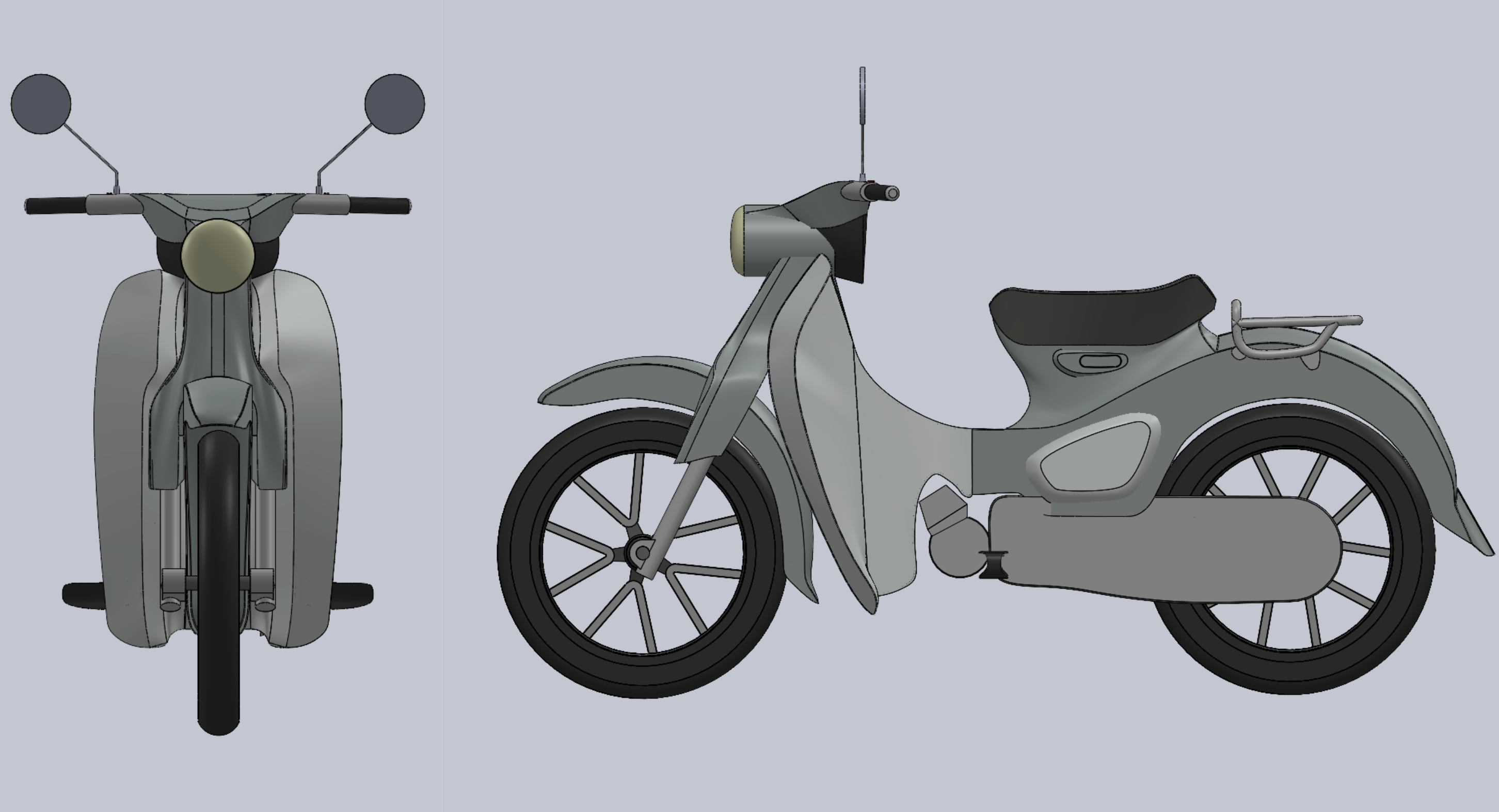
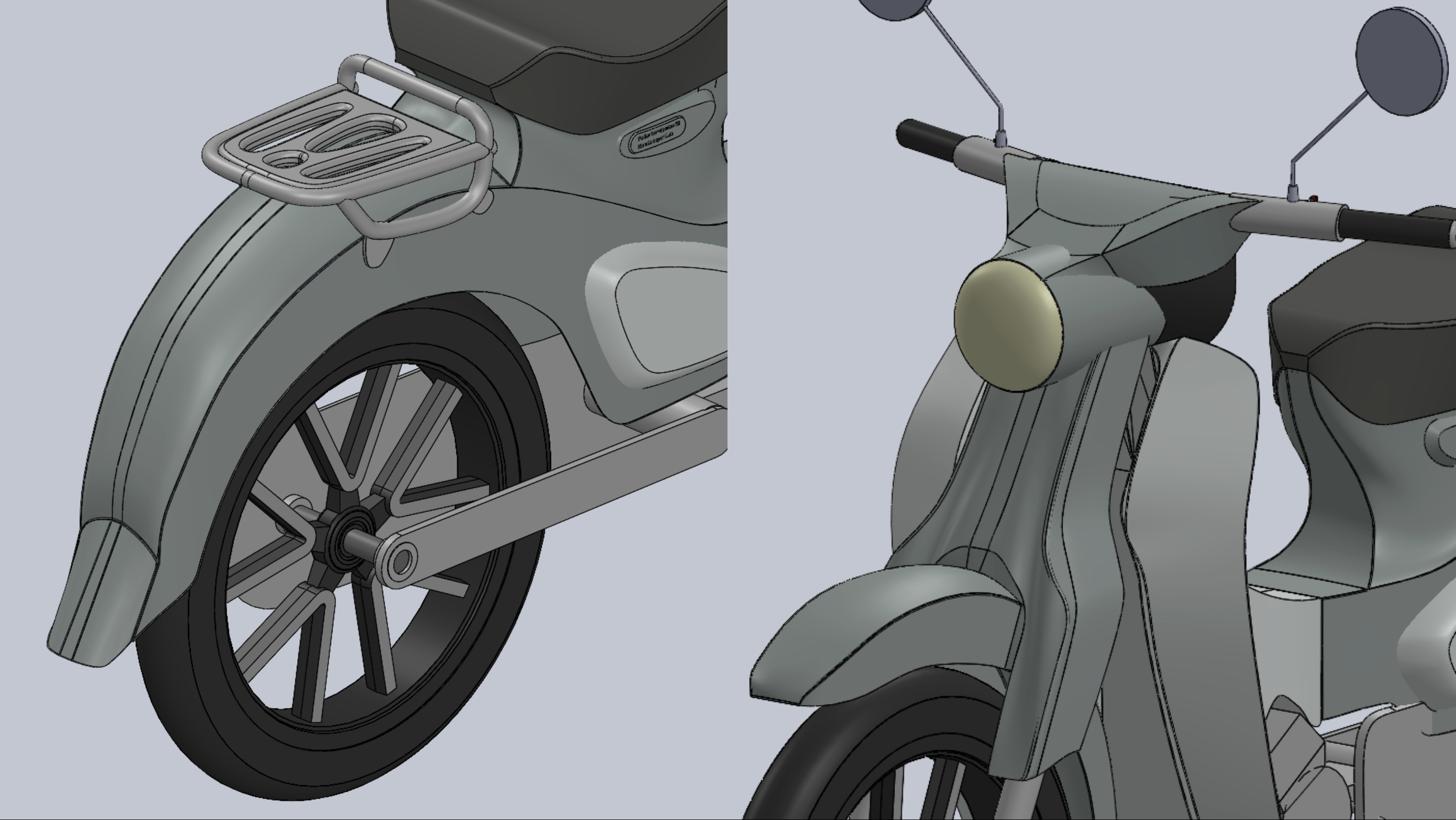
School Design Project
Objective: Recreate a 2021 Honda Super Cub in SolidWorks as a complex CAD modeling exercise
requiring surface features, curved body panels, and detailed component modeling.
Results: Modeled the Super Cub body lines and secondary features including the storage rack,
side mirrors, wheels, and fork assembly, building early experience with advanced SolidWorks tools.
CONTACT
I am currently seeking full-time mechanical engineering opportunities in design, manufacturing, product development, testing, and production support.
parkerlennig@gmail.com